Sony Polarization Sensor announced

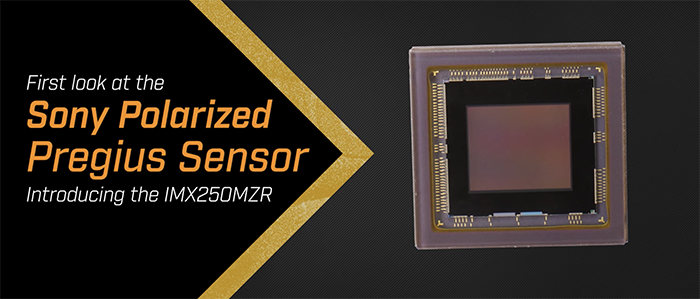
The 5 MP IMX250MZR is Sony’s first machine vison sensor with onboard polarization. In this video, you will see a demonstration of the sensor, including two of its time saving capabilities.
Here is the full press text via Sony-semicon.co.jp.
Polarization Image Sensor
Diagonal 11.1 mm (Type 2/3) Approx. 5.07M-Effective Pixel Monochrome/Color Polarization CMOS Image Sensor
 IMX250MZR / MYR
Polarization Image Sensor with Four-Directional on-chip Polarizer and global shutter function
Sony Semiconductor Solutions has launched a polarization image sensor (polarization sensor): 3.45µm, 5.07M-Effective Pixel with four-directional polarizer formed on the photodiode of the image sensor chip targeting the industrial equipment market*1.
In addition to the brightness and color*2, this image sensor can capture polarization information which can not be detected by normal image sensor. This polarization sensor can expand various possibilities in the industrial field such as inspection when visualization and sensing are difficult.
- *1. IMX250MYR(color) is planned to be launched in December 2018(As of 20th September 2018)
- *2. IMX250MYR(color) only.

Polarsens is a CMOS Image Sensor pixel technology that has several different angle polarizer formed on chip during the semiconductor process allowing highly accurate alignment with pixel.
 Polarizer image
Source: Sony, IEDM2016, Lecture number 8.7
- *Polarsens and
 are trademarks of Sony Corporation.
Characteristic
- Four-Directional Polarizer formed on chip
- Global shutter function
- High frame rate
- ROI mode, Trigger mode
Four directional polarizer is formed on the image sensor
IMX250MZR/MYR can capture a four directional polarization image in one shot by the four directional polarizer (Fig.1). It can calculate the direction of polarization and the degree of polarization(DoP) based on the intensity of each directional polarization. Combining with subsequent signal processing, it can capture polarization information*3 in real time*4.
- *3. Degree of Polarization and Direction of Polarization
- *4. Subject to subsequent signal processing power.

Fig.1. Structure
Polarizer is formed on chip under the on-chip lens layer
With conventional types of polarization sensors, the polarizer is attached on top of the on-chip lens layer (Fig.2), however with Sony Semiconductor Solutions’ polarization sensor the polarizer is formed on chip under the on-chip lens layer (Fig.3). A shorter distance between the polarizer and the photodiode improves the extinction ratio*5 and the incident angle dependence.
Since the polarizer is formed during the semiconductor process, form and formulation of polarizer, uniformity, mass productivity and durability are excellent compared to conventional polarization sensors. Furthermore, Sony Semiconductor Solutions’ Polarization sensor is covered with an anti-reflection layer which helps to reduce reflectance and avoids poor flare and ghost characteristics.
- *5. Extinction Ratio
Extinction ratio is a specification to measure polarization The extinction ratio of polarization image sensor is the ratio between the sensitivity of transmission axis light and the sensitivity of extinction axis light (the sensitivity of transmission axis light / the sensitivity of extinction axis light). The higher the number, the better the specification and performance.
Structure Comparison

Fig.2. Structure of Conventional Polarization sensor

Fig.3. Structure of Sony Semiconductor Solutions’ Polarization sensor
Global Shutter function
Industrial applications require imaging of fast-moving subjects. However, existing CMOS image sensors are unable to accurately identify fast-moving subjects due to the focal plane distortion as a result of the rolling shutter operation. The IMX250MZR/MYR addresses this issue by providing an analog memory inside each pixel and realizing a global shutter function to enable high-picture-quality imaging without focal plane distortion.
High Frame Rate
The column-parallel A/D conversion technology of Sony CMOS image sensors is used to realize high-speed imaging of up to 163.4 [frame/s] (ADC 8-bit) for the IMX250MZR/MYR. This enabled further increasing the processing speed for industrial applications.
ROI mode and trigger mode
The IMX250MZR/MYR are equipped with a variety of functions needed for industrial applications, such as ROI mode and trigger mode. ROI mode crops arbitrary areas, and up to 8 × 8 = 64 locations can be set. Various exposure methods are provided for trigger mode, which controls the exposure time using an external pulse.
What is polarization?
Light has physical elements : brightness (amplitude), color (wavelength) and polarization (vibration direction). Lights from the Sun or fluorescent lamps vibrate in various directions and is called unpolarized light.
 Fig.4.
IMX250MZR/MYR has wire-grid polarizers. Parallel light against polarizer passes through it and perpendicular light is cut off at the polarizer.
Degree of Polarization and Polarization Direction
Polarization has two physical information, which are the degree of polarization and the direction of polarization. This information can be used for various applications such as surface scratch detection, particle inspection, distortion and shape recognition which has traditional been difficult to detect.
Example of Degree of Polarization (DoP)
The light is reflected by the surface of the object in polarized and unpolarized lights. The DoP of the reflected light depends on the surface condition (material, color, roughness etc.) and the angle of reflection.

Fig.5. Normal image

Fig.6. Degree of Polarization image
In the Degree of Polarization image (Fig.6) the white is high polarization and black is low polarization.
As example, the stich is easily visible due to the difference in the degree of polarization of the thread and leather.
Example of Polarization Direction
Polarization direction provides the direction information of reflected plane of an object.

Fig.7. Normal image

Fig.8. Polarization Direction image
The direction of polarization image (Fig.8) shows the angle of the polarization direction in color using HSV color mapping (Fig.9).
In this example, the upper side of the cube is highlighted in light blue meaning that the angle of the polarization direction is 90 degree (according to Fig.9).
 Fig.9. HSV color mapping
Sample image
Glass inspection (scratch and stain)

Fig.10. Normal image

Fig.11. Degree of Polarization image
These examples show dents and dust on a homogenous glass plane. We can easily find scratches and stains (fingerprint and dust) due to differences in the degree of polarization. (Fig.10,11)
Tablet filling inspection

Fig.12. Normal image

Fig.13. Degree of Polarization image
Thanks to the difference in the degree of polarization between the tablet and the aluminum package, it is easy to identify whether the tablets are filled in or not. (Fig.12,13)
Distortion inspection

Fig.14. Normal image

Fig.15. Polarization Direction image
With the information of direction of polarization, we can identify both distortions and the direction of distortion of the plane. (Fig.14,15)
Removal reflection

Fig.16. Normal image

Fig.17. Removed reflection image
The information of polarization can be used to remove reflections(Fig.16,17). IMX250MZR/MYR has a four-directional polarizer which can simultaneously remove reflection in multi planes.(Fig.17)
All images were generated by a bundled software of IMX250MZR/IMX250MYR evaluation board.
| Item | IMX250MZR/MYR | |
|---|---|---|
| Pixel | Four-directional Polarization | |
| Image size | Diagonal 11.1 mm (Type 2/3) progressive scan mode Diagonal 7.7 mm (Type 1/2.35) Full-HD mode |
|
| Number of effective pixels | 2464 (H) × 2056 (V) approx. 5.07M pixels |
|
| Unit cell size | 3.45 µm (H) × 3.45 µm (V) | |
| Optical blacks | Horizontal | Front: 0 pixels, rear: 0 pixels |
| Vertical | Front: 10 pixels, rear: 0 pixels | |
| Input drive frequency | 37.125 MHz / 54.0 MHz / 74.25 MHz | |
| Package | 226-pin LGA | |
| Supply voltage VDD (Typ.) | 3.3 V / 1.8 V / 1.2 V | |
| Item | IMX250MZR/MYR | Remarks | |
|---|---|---|---|
| Sensitivity (monochrome) | Typ.[F8] | 342 mV | 3200 K, 706 cd/m2、 1/30s accumulation |
| Sensitivity (color) | Typ.[F5.6] | 430mV | |
| Saturation signal | Min. | 1001 mV | Tj = 60 °C |
| Product name | Drive mode | Recommended number of recording pixels | ADC [bit] |
Frame rate (Max.) [frame/s] |
|---|---|---|---|---|
| IMX250MZR/MYR | Progressive scan | 2448 (H) × 2048 (V) approx. 5.01M pixels |
12 | 89.5 |
| 10 | 144.7 | |||
| 8 | 163.4 | |||
| Full-HD | 1920 (H) × 1080 (V) approx. 2.07M pixels |
12 | 120.0 | |
| 10 | 120.0 |
Fig.18. IMX250MZR Omnidirectional Extinction Ratio (Min.)
 Subject to test and environment conditions
VOICE
IMX 250 MZR / MYR are the Sony’s first and world’s smallest*6 pixel size (IMX 250 MZR / MYR) and the world’s first*6 color (IMX 250 MYR) polarization image sensor thus far as the commercially available product. By creating a unique air gap structure in the polarizer, it enables excellent polarization properties and sensitivity in a broad band from visible to near infrared. It also has an advantage of excellent image quality in various light source environments by introducing the world’s first*6 anti-reflection layer to reduce flare and ghost for polarization sensor.
In order to achieve the required polarization properties and sensitivity, it is necessary to control the each wire grid’s shape very precisely in units of nanometers. When I realized the fact by simulation, I was worried if it could actually be manufactured. And we did not know whether a unique air gap structure can be created without manufacturing and quality assurance issues. When launching the polarization evaluation environment, the definitions of the words were different from each other, like the origins of the polarization angle, the direction of rotation, whether polarized light is represented by electric field or magnetic field, and so on. I am very glad to know that cleared all these tasks, confirmed the required properties, and now ready to ship. I especially appreciate the factory members which managed to realize the idea which was initially thought impossible.
- *6. As of September 2018 (based on Sony Semiconductor Solutions’ research)